- Products
- Couplings
- Clutches
- Cross & Morse
- Overload Clutches
- Freewheel Clutches
- Industrial Ratchet Freewheels and Adaptors
- "M" Series Sprag Clutches
- Backstop Types B200 & B500
- Roller Ramp Clutches CNAS/CNFS
- Sprag Clutches CKK/CSK
- Roller Ramp Clutches AA, AEF, ANF and ANR
- Roller Ramp Clutch with Ball Bearings AGF/AGFN
- Compact Freewheel Clutches KI, ASK and GFK
- Sprag Elements - BW units
- Backstop Clutches CR/BV, CR/BT and CR/BW
- Sprag Clutches PB & HT
- Torque Limiters
- Miki Pulley
- Torque Limiters
- Electromagnetic Clutches & Brakes
- 102 Models (micro clutches)
- CYT Models (Custom micro clutches)
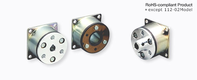
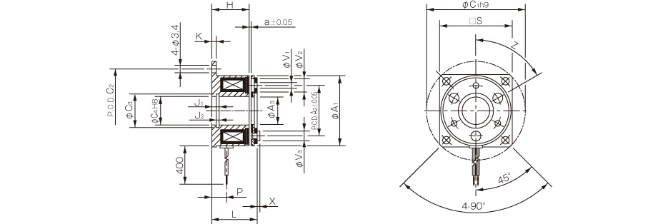
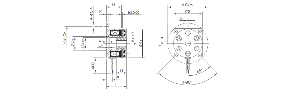
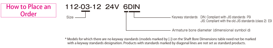
- 112 Models (Micro brakes)
- 101/CS Models (Clutches)
- 111 Models (brakes)
- CSZ Models (Clutches)
- BSZ Models (Brakes)
- 125 Models (Clutches and brakes)
- 121(20G) Types (Clutches and brakes)
- 126 Models Clutch/Brake Units - Motor-coupled Type
- CBW Models Clutch/ Brake Units - Speed Reducer-Integrated Type
- CMW Models Clutch/Brake Units - Motor/Speed Reducer-Integrated Type
- 121(10G) Types Double clutches
- 122 Models (Double clutches/brakes)
- Electromagnetic Spring-Actuated Brakes
- Cross & Morse
- Vibratory
- Controllers
- About
- Industry Partners
- News Articles
- Contact